MICA Band LEAD TERMINATION & mounting configuration oPTIONS
Mica Band heaters are constructed with a mica core wound with wire, the core is then bent into the requested diameter. Mica bands can be manufactured to your specifications. These heaters are used to heat barrels or cylinders. Numerous variations of construction, termination, and lockup are shown below.
lead termination options

Nozzle heating applications design with 12” standard lead length.

Standard lead wires exiting 180° from gap.
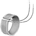 Single conductor metal braid over lead wire. Offers most practical solution to abrasion problem. 12″ braid with 14″ overall length leads are standard.
Metal Braided Leads

Double conductor metal braid over lead wires. 12″ braid with 14″ overall length leads are standard. Specify alternate exit position.
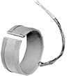
Double conductor metal braid exiting from edge 180° from gap.
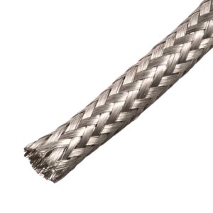 Metal Braid braid is most commonly specified in applications where leads may be subjected to abrasion due to movement of the application. Lead wires may be rubbing together or passing over sharp objects.
Armor Cable Leads

Double conductor metal braid over lead wires. 12″ braid with 14″ overall length leads are standard. Specify alternate exit position.

Double conductor metal braid exiting from edge 180° from gap.
 SS Armor Cable used over leads in areas where more protection is necessary. Selected for similar applications as the stainless steel braid, in addition to applications where non-fluid contamination may come in contact with the leads. This lead protection is not as flexible as the braid. Stainless steel square lock construction.
SCREW TERMINALS
 Standard position under 2-1/2″ wide.
 Standard position over 2-1/2″wide.
 10-32 thread requires 1/2″ clearance from cylinder.
 Standard with terminal box
mounting / lockup configurations
 Hinged Half Band is convenient when two piece heaters are required. Mounting flange lockup and T2 screw terminals. Available with any termination or mounting arrangement.
 Half Band eases installation in difficult situations. Shown with T8 Terminals and full bypass strap lockup for terminal clearance Available with any termination or mounting arrangement
 Probe holes and cutouts specify location in degrees from center of gap and size or provide drawing. Often a larger gap (3/4″ – 1″) will serve the same purpose. Standard gap is 1/4”.
 Split case allows heater to be opened one time for mounting. Available with any termination or mounting arrangement, full strap lockup.
 Strap-made from a low expansion alloy to tighten around the whole circumference of the heater with 5/16 socket head bolt. Low Profile: H =1/4″, 1/2″ wide (Supplied on 3″ I.D. and less). Standard Profile: H = 3/8″, 5/8″ wide (supplied on 3-1/8″ I.D. and larger). Also available with hose clamp or punch lock strap.
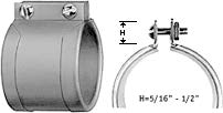 Mounting Flange is a secondary means for mounting where a built-in method is preferred with 5/16 socket head bolt.
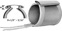 Wedge Mount-for applications where an extremely low profile is required or where access is limited. Standard with 16” leads.
 Standard Profile Barrel Nut Assembly Welded to Sheath with 10-32 screw.
 Quick Release Assembly with Spring Loaded Screw Assembly Welded to Sheath with 1/4 – 20 screw.
 1-1/4″ Wide Barrel Assembly Welded to Sheath with 5/16 – 18 socket head screw.
 Low Profile Barrel Nut Assembly Welded to Sheath with 6-32 screw.
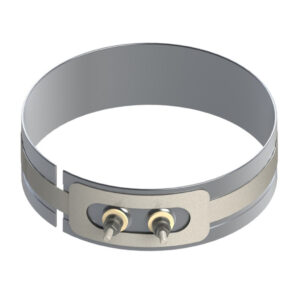 Jumper or Bypass Strap is best suited for one piece expandable bands. This strap style is available on any post terminal or lead wire construction. This heater band style offers the greatest power draw among most common clamping styles.
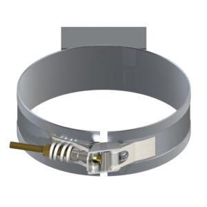 The Mica Band Latch and Trunion style offers the flexibility of adjust to thermal expansion with its spring loading on the screws. The latch construction allows for ease of installation of band heater on larger diameter cylinders.
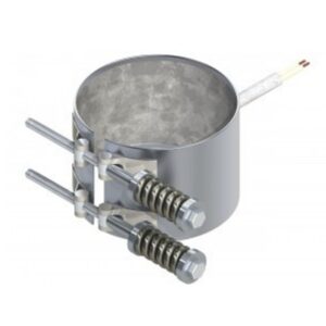 Tig welded barrel nuts with spring loaded clamp – is used during start-up to ensure the heater fits securely on large barrels. Stainless steel top metal is required. This band heater option is mandatory on vertical applications.
Note: When ordering this Tig Welded Barrel Nuts design – specify the spring loaded clamping feature.
mounting / lockup configurations
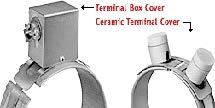
Terminal Box Cover:
2″ H x 1-1/2″ W x 2″ L. Also available in a 2-1/4″ H x 2-1/16″ W x 4-1/2″ L terminal box for larger clearance to terminals.
Ceramic Terminal Cover:
7/8″ high x 3/4″ O.D. for 10-24 thread.
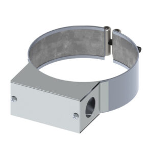 Terminal Box is attached to the heater to cover and protect the terminals from damage and provide a safety measure.
Terminal Box Attributes:
- Available on heaters from 88 mm (3.5 in.) diameter or larger.
- A Conduit may be attached to the box through 22 mm (0.875 in.) diameter holes in the ends of the box.
- Available on one or two piece stock Thinband heaters.
Note: Terminal Box specifications must be presented in writing when requesting an order for this style band heater.
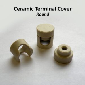 These ceramic covers provide great protection against electric shock. Our Ceramic Terminal Covers are sold separately.
Thread Sizes: 10-24 Thread, 10-32 Thread, 1/4-20 Thread, Metric 5 mm
plug options
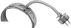 Plug can be attached to any lead configuration.
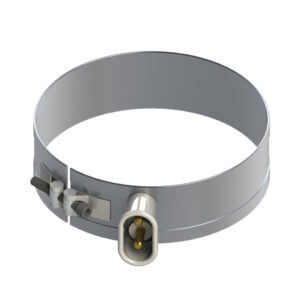
This Europlug Termination is ideal when frequent disconnection is required.

European High Temperature Plug: Dimensions-1-3/8″ H x 3-7/16″ L x 1-7/8″ W

Mating Receptacle for plugs


