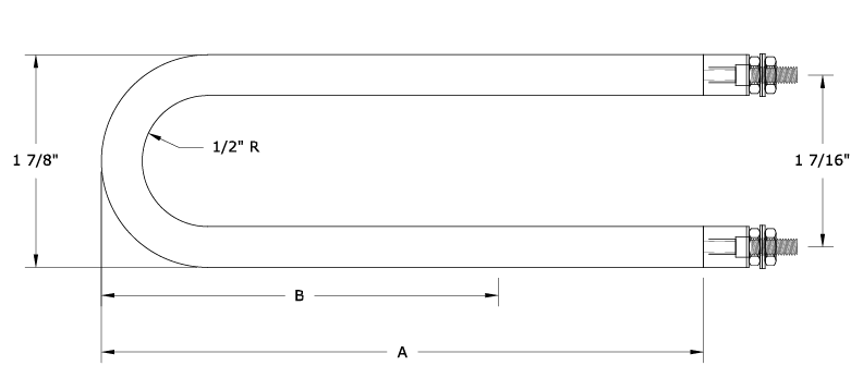
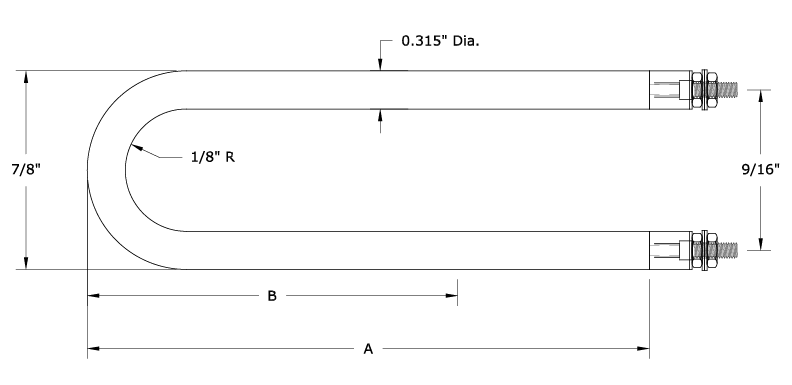
HAIRPIN TUBULAR HEATING ELEMENTS
|
HEATH LENGTH “A”
|
HEATED LENGTH “B”
|
WATTS
|
VOLTS
|
|
13 ½
|
10 ½
|
750
|
240 480
|
|
19 1⁄16
|
14 1⁄16
|
1000
|
240 480
|
|
21 ⅜
|
18 ⅜
|
1250
|
240 480
|
|
26 ¼
|
21 ¼
|
1500
|
240 480
|
|
34 ¼
|
29 ¼
|
2000
|
240 480
|
|
41 ¾
|
36 ¾
|
2500
|
240 480
|
|
49
|
44
|
3000
|
240 480
|
|
53
|
48
|
3333
|
240 480
|
|
66
|
61
|
4167
|
240 480
|
|
79
|
74
|
5000
|
240 480
|
|
SHEATH
LENGTH “A” |
HEATED
LENGTH “B” |
WATTS
|
VOLTS
|
|
7 ⅝
|
4 ⅞
|
250
|
120
240 |
|
10 ⅝
|
7 ⅞
|
375
|
120
240 |
|
13 ⅝
|
10 ⅞
|
500
|
120
240 |
|
21 ⅛
|
18 ⅜
|
750
|
120
240 |
|
27 ¾
|
25
|
1000
|
120
240 |
|
40 ¼
|
37 ½
|
1500
|
120
240 |
TUBULAR HEATING OPTIONS
THREADED FITTINGS
Threaded fittings are furnished with nuts and optional fiber gaskets, washers and lockwashers. Fittings are silver soldered, welded or mechanically pressed (staked) to the sheath. Welding requires sheath and fitting material compatibility. Standard elements may be provided with two fittings, one for each terminal end. Two-pass elements may be provided with only one fitting.
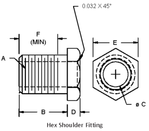
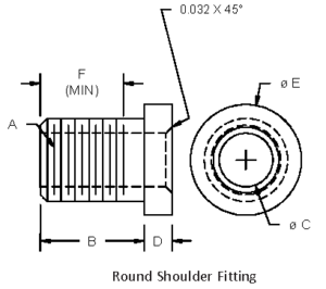
THREADED FITTING CHART
| C Element Diameter |
Fitting Part No. | Shoulder Type | Material | A Thread Size |
B Length |
D Shoulder Thk |
E Head Size |
F Min. Thrd. Length |
| 0.250/0.260 | 60000425 | Hex | SST | 7/16-20UNF | 0.56 | 0.13 | 0.63 | 0.425+ |
| 0.250/0.260 | 60000428 | Hex | BRS | 1/2‐20UNF | 0.50 | 0.13 | 0.75 | 0.43 |
| 0.250/0.260 | 86-2-C-3 | Round | BRS | 1/2‐20UNF | 0.63 | 0.13 | 0.75 | 0.55 |
| 0.26 | 86-3-C-74 | Hex | BRS | 1/2‐20UNF | 0.69 | 0.19 | 0.75 | 0.61 |
| 0.32 | 60000326 | Hex | SST | 7/16-20UNF | 0.56 | 0.13 | 0.63 | 0.425+ |
| 0.32 | 1007121 | Round | BRS | 7/16-28UNEF | 0.56 | 0.31 | 0.75 | 0.51 |
| 0.32 | 86-22-C-1 | Hex | BRS | 1/2‐20UNF | 0.50 | 0.19 | 0.75 | 0.43 |
| 0.32 | 86-22-ZC-2* | Hex | BRS | 1/2‐20UNF | 0.50 | 0.19 | 0.75 | 0.43 |
| 0.32 | 86-3-UZ-1 | Hex | 303 SST | 1/2‐20UNF | 0.63 | 0.13 | 0.75 | 0.488+ |
| 0.32 | 60000431 | Round | SST | 1/2‐20UNF | 0.81 | 0.13 | 0.75 | 0.675+ |
| 0.32 | 1007139 | Round | BRS | 1/2‐20UNF | 0.88 | 0.31 | 0.75 | 0.80 |
| 0.32 | 86-37-C-1 | Hex | BRS | 1/2‐20UNF | 1.00 | 0.25 | 0.75 | 0.93 |
| 0.32 | 1007219 | Round | BRS | 9/16-18UNF | 0.50 | 0.13 | 1.00 | 0.42 |
| 0.32 | 1007142 | Round | BRS | 5/8-18UNF | 0.50 | 0.31 | 1.00 | 0.42 |
| 0.32 | 86-62-C-1 | Hex | BRS | 5/8-18UNF | 0.75 | 0.19 | 0.88 | 0.67 |
| 0.32 | 60000384 | Hex | SST | 5/8-18UNF | 0.81 | 0.13 | 0.88 | 0.73 |
| 0.38 | 60000324 | Hex | BRS | 1/2‐20UNF | 0.56 | 0.13 | 0.75 | 0.49 |
| 0.38 | 60000198 | Hex | 303 SST | 9/16-18UNF | 0.69 | 0.13 | 0.75 | 0.542+ |
| 0.38 | 86-3-UZ-81 | Hex | 303 SST | 9/16-18UNF | 1.00 | 0.13 | 0.88 | 0.854+ |
| 0.43 | 86-47-C-1 | Round | BRS | 9/16-18UNF | 1.00 | 0.25 | 0.75 | 0.92 |
| 0.43 | 86-36-C-2 | Hex | BRS | 5/8-18UNF | 0.50 | 0.19 | 0.88 | 0.42 |
| 0.43 | 60000320 | Hex | SST | 5/8-18UNF | 0.63 | 0.13 | 0.88 | 0.48 |
| 0.43 | 86-36-C-1 | Hex | BRS | 5/8-18UNF | 0.75 | 0.19 | 0.88 | 0.67 |
| 0.43 | 60000396 | Hex | SST | 5/8-18UNF | 1.00 | 0.13 | 0.88 | 0.854+ |
| 0.43 | 86-3-C-7 | Hex | BRS | 5/8-18UNF | 1.06 | 0.19 | 0.88 | 0.98 |
| 0.43 | 60000352 | Hex | BRS | 3/4-16UNF | 0.81 | 0.19 | 1.00 | 0.72 |
| 0.43 | 60000337 | Hex | SST | 3/4-16UNF | 1.06 | 0.19 | 1.00 | 0.97 |
| 0.48 | 1007127 | Round | BRS | 5/8-18UNF | 0.56 | 0.31 | 1.00 | 0.48 |
| 0.48 | 1006846*** | Round | STEEL | 5/8-18UNF | 0.56 | 0.13 | 1.00 | 0.417+ |
| 0.48 | 1007118 | Round | BRS | 5/8-18UNF | 0.81 | 0.31 | 1.00 | 0.73 |
| 0.48 | 1007276 | Round | SST | 5/8-24UNEF | 0.75 | 0.13 | 1.00 | 0.625+ |
| 0.48 | 1007279 | Hex | SST | 3/4-16UNF | 0.38 | 0.19 | 1.00 | 0.28 |
| 0.48 | 1000058** | Hex | STEEL | 3/4-16UNF | 0.50 | 0.13 | 0.88 | 0.41 |
| 0.48 | 1007225 | Hex | BRS | 3/4-16UNF | 0.88 | 0.25 | 1.00 | 0.78 |
| 0.48 | 1007228 | Hex | SST | 3/4-16UNF | 0.88 | 0.25 | 0.88 | 0.78 |
| 0.48 | 1007273 | Hex | SST | 3/4-16UNF | 1.06 | 0.19 | 1.00 | 0.97 |
| 0.49 | 60000389 | Hex | BRS | 5/8-18UNF | 0.50 | 0.13 | 0.88 | 0.42 |
| 0.49 | 60000138 | Hex | SST | 5/8-18UNF | 0.88 | 0.19 | 0.88 | 0.729+ |
| 0.49 | 60000317 | Hex | SST | 3/4-16UNF | 0.56 | 0.13 | 1.00 | 0.47 |
| 0.49 | 60000070 | Hex | SST | 3/4-16UNF | 1.06 | 0.19 | 1.00 | 0.97 |
| 0.63 | 60000410 | Hex | STEEL | 7/8-14UNF | 1.00 | 0.13 | 1.13 | 0.83+ |
| 0.63 | 60000373 | Hex | SST | 7/8-14UNF | 1.13 | 0.13 | 1.13 | 0.955+ |
| 0.63 | 60000008 | Hex | SST | 7/8-14UNF | 1.38 | 0.13 | 1.13 | 1.205+ |
| 0.63 | 60000375 | Round | STEEL | 7/8-14UNF | 1.88 | 0.13 | 1.25 | 1.705+ |
+ Fitting has a 1/16” weld projection not included in the “F” dimension shown. Consult factory for details.
* Tin plated brass
** This fitting is copper plated steel, normally furnished on finned tubular elements with palnut type locknuts standard. Gaskets are not furnished unless specified.
*** Nickel plated steel
Other fittings available, contact factory.
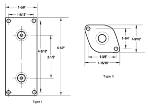
MOUNTING PLATES
MOUNTING PLATES
Mounting plates provide a simple, convenient means of holding elements in place in an airstream and other applications where the element is not immersed in a liquid. Stainless steel plates are mechanically pressed (staked) or tack welded to sheathed elements.
The mounting plates shown to the right are standard configurations for .475” diameter elements. Consult factory for other diameters and configurations.
| Heating Element Configuration |
Mounting Plate | |
| Type | Material | |
| 2-1/2” C-C U-Bent | I | Stainless |
| Straight or Two-Pass | II | Stainless |
terminal assembly options
Terminal # 1
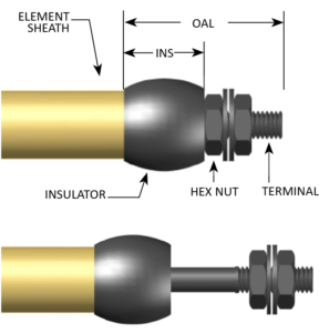
Threaded Terminal (standard)
| Description: Stainless steel stud with threaded length Optional: Insulators available in silicone rubber (std) or optional mica or ceramic where available Use: For lead attachment in the field. 600V rating |
 |
| Thread Sizes* | OAL Standard | INS Standard (Insulator Dim) |
| 6-32 | 1” | 0.50” |
| 8-32 | ||
| 10-32 | ||
| 1/4-20 |
* 6-32 thread is standard for .250 and .260
Element Diameters, 10-32 thread is standard for all other Diameters.
Other thread size, INS and OAL lengths available upon request.
Terminal # 2
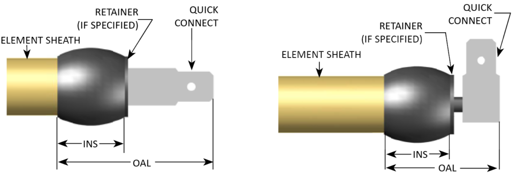
Quick Connect Terminal
|
Description: Optional: Use: |
 |
| oltage Range |
OAL Standard (Straight terminal) |
OAL Standard (90 Deg terminal) |
INS Standard (Insulator Dim) |
| 0-250V | 0.75” | 0.813” | 0.25 |
| 251-600V | 1” | 1.063” | 0.5 |
Terminal # 3
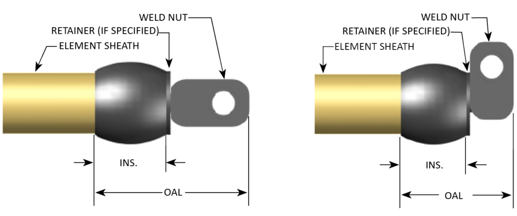
Weld NutDescription: Use: |
 |
| Voltage Range |
OAL Standard (Straight terminal) |
OAL Standard (90 Deg terminal) |
INS Standard (Insulator Dim) |
| 0-250V | 0.813” | 0.563” | 0.25 |
| 251-600V | 1.063” | 0.813” | 0.5 |
Terminal #4
Neoprene Insulated LeadsDescription: Use: |
PVC Insulated LeadsDescription: Use: |
Silicone Insulated Leads with Glass Braid (SRG)Description: Use: |
 |
Type TGGT LeadsDescription: Use: Mica Insulated Leads with Glass Braid (MGT)Description: Use: |
| Standard Supplied Wire Gauge | Limit Amps |
| 18 | 10 |
| 16 | 15 |
| 14 | 20 |
| 12 | 30 |
terminal # 5
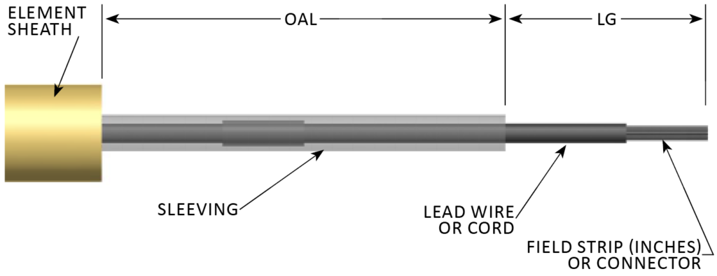
Defrost TerminalDescription: OR Epoxy Filled Metal Cup TerminalDescription: Use: |
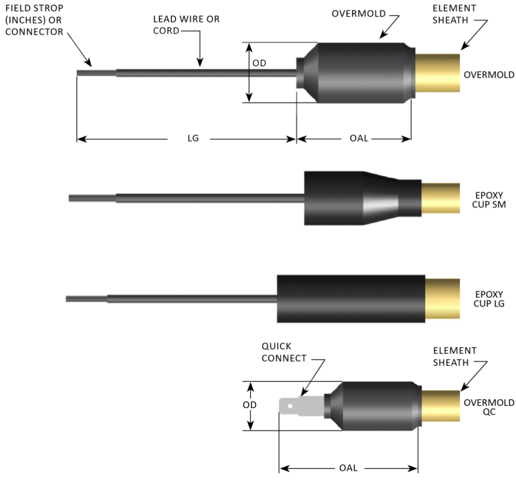 |
| Type | Material | Type | Element Sizes | OD | OAL | Location | Description |
| Overmold QC | Neoprene | One-Pass | 0.250 – 0.315 | 0.4375 | 1.0625 | Moist | T Series |
| Epoxy Cup SM | Epoxy/Metal | One-Pass | 0.315 | 0.5625 | 1.25 | Wet | Blank Series |
| Epoxy Cup LG | Epoxy/Metal | One-Pass | 0.475 | 0.5625 | 1.75 | Wet | Blank Series |
| Overmold | Neoprene | One-Pass | 0.250 – 0.375 | 0.4375 | 1.75 | Wet | W Series |
| Overmold | Neoprene | One-Pass | 0.430 – 0.490 | 0.75 | 1.75 | Wet | W Series* |
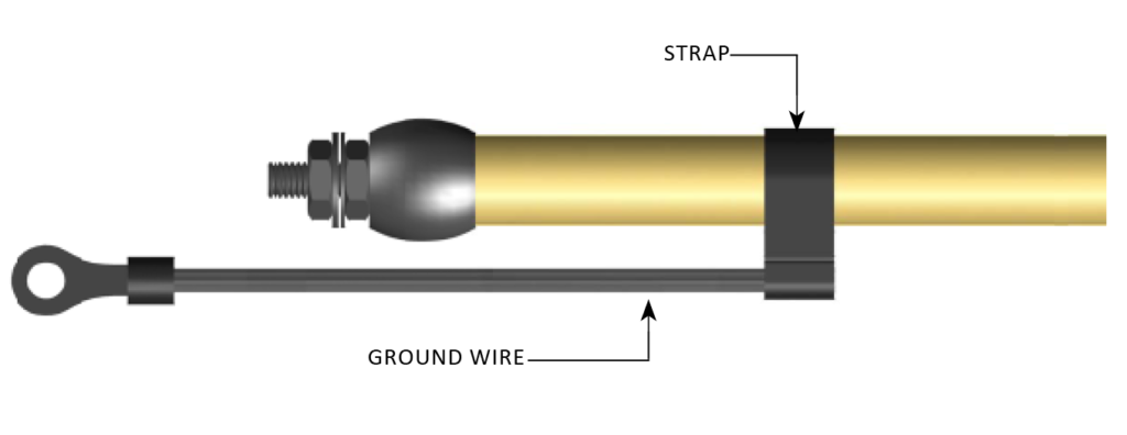
Grounding Strap (Optional)
|
Description: Use: |
 |
End Seal Options
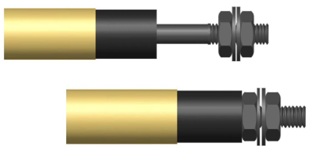
End Seal #1:Epoxy BarrierDescription: Use: |
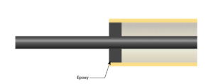 |
End Seal #2:RTV BarrierDescription: Use: |
 |
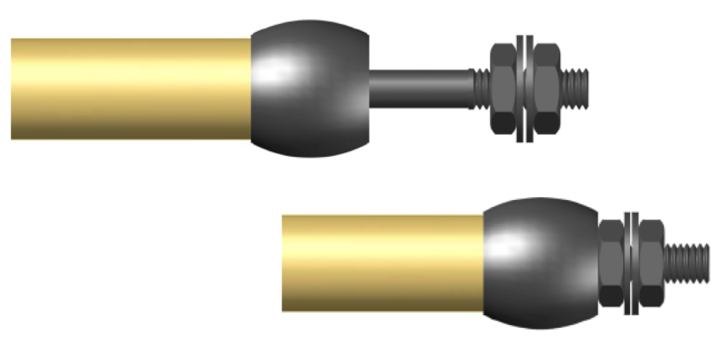
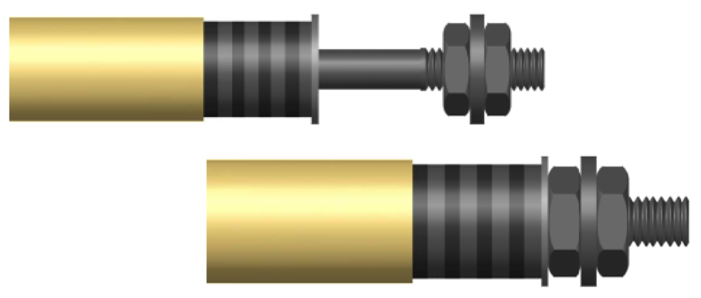
End Seal #3:Hermetic SealDescription: Use: Element Sheath: |
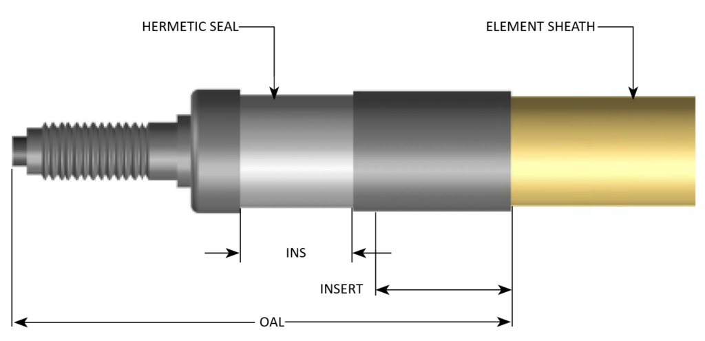 |
| Element Sheath Diameter | INS Standard (Integral Ceramic Insulator Dim) | OAL Standard |
| 0.430 | 0.5 | 2.125” |
| 0.475 | 0.5 | 2.125” |
| Alternate element sheath diameters available upon request. | ||
Insulator Options
Insulator #1:Silicone Rubber (standard)Description: |
 |
Insulator #2:MicaDescription: Applications where terminal temperatures do not exceed 900oF. 1/4” thick insulation furnished up to 250V; 1/2” thick up to 600V. |
 |
End Seal #3:Insulator #3:CeramicDescription: |
 |