COIL HEATERS
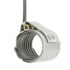
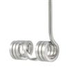
Coil heaters are also referred to as cable heaters, hot runner nozzle heaters, spring heaters, hot sprue heater, or micro tubular heaters. Though often found in a spiraling or winding shape, a hot runner coil heater is not named after the shape of its exterior; the name refers to the resistance wire inside the heater that has a small winding pattern throughout the length of the heater.
- Range from Micro Mini to Maxi Coil heaters so you can choose the right size and wattage capability for your application
- Includes internal thermocouple options or may be used with external thermocouples
- May be wound to directly fit a nozzle, embedded in a thermal mass for nozzle, formed into a grove for three dimensional heating, or can work as an easy-to-remove cartridge heater alternative
- May be manufactured with longer cold sections to allow higher temperature applications to utilize flexible leads and moisture resistance
FLAT COIL HEATERS
The Flat Coil Heater set the standard with respect to precise fit and profiling to optimize the performance of nozzles and other mating components. Available with or without internal thermocouple — Type J or Type K. At 2.5mm(.098”) in height the flat coil heater can accommodate today’s design objective of placing nozzles closer to waterlines and minimizing material usage. With a superior width of 3.4mm(.134”) surface contact is maximized resulting in less required heated length and more watts per linear inch.
STS offers a wide range of performance enhancing options including:
- Outside sheath to improve heating efficiency
- Inside/Outside sheath with sealed end rings to prevent contaminates shortening heater life
- Embedding in brass to create high thermal mass surrounding the heater improving high temperature performance, and heater life
- Moisture resistant transition head
- High temperature lead and potting options
- Flexible cold section
- Wide variety of standard and custom lead exit options
We can coil heaters from stock and ship next day. Or build to order in 5 business days.
LOW PROFILE COIL HEATERS
The 1.8 x 3.2 coil heater delivers the performance of standard coil heaters in a thinner profile. The 1.8mm height allows system designers to place drops closer to waterlines, enabling a smaller footprint. The 3.2mm width delivers higher wattage per linear inch compared to mini coils.
The 1.8 x 3.2mm coil heater single transition head can be built with optional moisture-resistant construction to reduce reliance on soft starting in high humidity environments. Where higher wattage is required in constrained spaces, the 1.8 x 3.2mm coil heater delivers the heating performance you need.
Technical Data
-
Profile: 1.8mm(.071”) Thick X 3.2mm(.126”) Wide
-
Thermocouple: Integrated type J or type K
-
Maximum Sheath Temperature: 1382 deg. F
-
Sheath Material: Cr-Ni Steel
-
Maximum Total Straight Length: 3000mm (118.11”)
-
Length Tolerance: Heated +/-1%; Unheated +/- 2.5%
-
Maximum Voltage: 250VAC
-
High Voltage Stability: 800 VAC
-
Wattage Tolerance: +/-10% (contact hotset for special)
-
Minimum Bending Radius: 8mm(.315”)
-
Watt Density: 38.7 Watts/In2
-
Insulation Resistance: >=5M Ohm @ 500 VDC (cold)
-
Leakage Current: <= 0.5mA @ 250 VAC (cold)
-
Length of Unheated Zone: 65mm(2.56”); 25mm(1.00”) Transition Head
PRESSED IN BRASS COIL HEATERS
Pressed in brass coil heaters deliver the benefits of cast in brass coil heaters and eliminate known problems associated with the casting process. Originally designed for the mass spectrometry market, pressed in brass coil heaters have measured 8% faster responding than cast in brass heaters. The machined path in the brass for the heater enables exact repeatability of heat profile. By never exposing the coil heater to molten brass there are no risks of shifted heater coils, or destruction of the thermocouple junction.
Once the brass component is designed and in stock, pressed in brass coil heaters can be delivered in 7 business days or less.
Flexible design options include internal, external “wound in” or external slotted type J or type K thermocouple
For OEM applications Nexthermal can heat profile a pressed in brass coil heater specifically to your nozzle.
- Can be built with a Micro, Mini, Flat, Low profile, or Round Nexthermal Coil Heater.
- Thermocouple not exposed to molten brass temperatures – Improved durability
- Faster responding heater due to eliminated air pockets than cast in brass
- Profile and heater orientation precisely repeatable
- OEM programs with 1 week delivery compared to traditionally 4-6 Week for cast in brass
- Potential for designing thin walled brass heaters to minimize OD impact
- Injection Molding
- Mass Spectrometry
- Air heating
- Medical
MINI COIL / MICRO MINI
The mini coil heaters and micro mini moil heaters are high performance heaters for smaller diameter nozzles and nozzle tips that can also be formed in grooves to create three dimensional heating applications. Due to the small diameter size, mini coil heaters and micro mini coil heaters are most frequently designed with a pressed on sheath, pressed into brass, or serve as the heat source for Hotlock, and Axial Clamp heaters.
- Proven durable heater for tight space constraints
- Wound with external TC
- Form in place heater
- Staggered or single transition head configurations
- Build to order ships in 6-8 business days (Shorter lead times possible)
- Profile:1.8mm(.071”) Round
- Profile:1.3mm(.051”) x 2.3mm(.091”) Mini
- Profile:1.1mm(.043”) x 2.3mm(.091) Micro Mini
- Profile:1.0mm(.039”) x 1.6mm(.063”) Micro
- Thermocouple: External type J or type K
- Maximum Sheath Temperature: 1382 deg. F
- Sheath Material: Cr-Ni Steel
- Length Tolerance: -.040”
- Maximum Voltage: 250VAC
- High Voltage Stability: 800 VAC
- Wattage Tolerance: +/-2%; +/-10% (contact hotset for special)
- Minimum Bending Radius: 3.18mm(.125”) for Round and Mini
- Minimum Bending Radius: 3mm(.1186mm(.236”) for Micro Mini and Micro
- Watt Density: 38.7 Watts/In2
- Insulation Resistance: >=5M Ohm @ 500 VDC (cold)
- Leakage Current: <= 0.1mA @ 253 VAC (cold)
- Length of Unheated Zone: Minimum 25.4mm(1.00”), Maximum 254mm(10.00”)
- Standard Connection : 72” Teflon Leads to 500 deg F
- Injection Molding
- Packaging
- Automotive
HOTLOCK® COIL HEATERS
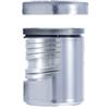
Introducing the next generation Hotlock mini coil heater. The new design utilizes a positive locking positioning ring and machined components to reduce manufacturing complexity. Installation is easy with a twist of the end cap ring the heater is secured into position on the nozzle, and with the integrated thermocouple slot located under the cap the thermocouple is precisely located. No tools are required for installation or removal.
The proven mini coil technology is at the heart of the Hotlock. This Hotlock design protects the mini coil heater with an inside, outside stainless sheath and enclosed end rings for superior durability. Standard IDs of .750”(19.05mm) and .875”(22.22mm) will be stocked with standard lengths, voltage, and wattages. Custom build to order Hotlocks can be manufactured in 2 weeks or less and will develop custom inside diameter Hotlocks for major OEM opportunities.
- Positive locking positioning
- Anti-Seize Coating for ease of removal
- Replaceable external thermocouple
- Profiled for more heat at the Tip
- Heater Sheath: CrNi Steel
- High Voltage Stability: 800VAC
- Insulation Resistance: >= 5M ohm at 500 VDC (Cold)
- Leakage Current: <= 0.5 mA at 250VAC (Cold)
- Wattage Tolerance: +/- 2%, +/- 4%, or +/-10%
- Maximum Voltage: 250V
- Standard Connection: 72” Teflon to 500 deg. F
- High Cavitation
- Caps and Closures
- Plastic Molding for the Cosmetic Industry
AXIAL CLAMP HEATER
Axial clamp mini coil heaters are a proven performer for high cavitation applications including pre-forms, caps and closures, and razors. The axial clamp heaters positively lock on the nozzle ensuring excellent heat transfer and durability. Adjustments can be made with a single front facing allen screw, greatly simplifying tightening and removal.
With flat mini coils in direct contact with the injection molding nozzle axial clamp heaters can be wound with more heater coils closer to the edge. This configuration improves responsiveness and heat profile.
- Positive locking positioning
- Single allen screw adjustment for tightening and removal
- Mini coils in direct contact with nozzle
- Close matching of Ohms so that multiple axial clamp heaters can be controlled with a single thermocouple
- Heater Sheath: CrNi Steel
- High Voltage Stability: 800VAC
- Insulation Resistance: >= 5M ohm at 500 VDC (Cold)
- Leakage Current: <= 0.5 mA at 250VAC (Cold)
- Wattage Tolerance: +/- 2%, +/- 4%, or +/-10%
- Maximum Voltage: 250V
- Standard Connection: 72” Teflon to 500 deg. F
| Standard Stock Axial Lock-up Heaters | ||||
|---|---|---|---|---|
| Diameter | Width | Watts | Volts | |
| “3/4” “(19.05mm)” | “1.2” “(30mm)” | 149W | 240V | |
| “3/4” “(19.05mm)” | “1.2” “(30mm)” | 268W | 240V | |
| “7/8” “(22.22mm)” | “1.2” “(30mm)” | 268W | 240V | |
| *All stock Axials can be re-fit with external wound in thermocouple for same or next day shipment. | ||||
FORMABLE COIL HEATER
The 4.0 mm, 3.18 mm, and 3.0 mm round coil heaters can be formed into two dimensional and three dimensional grooves for space constrained applications, converting a functional component into a heat source. On new product development — round coil heaters offer unparalleled flexibility.
ROUND COIL HEATER
STS continues support of round coil heaters that revolutionized the injection molding industry in 1980, for nozzle heating applications. The compaction and flexibility of the round coil heaters are core attributes of this time proven technology. Emerging applications of the round coil heater include pressed in brass for nozzle heating, form in place for plate heating and form in place for three dimensional heating.
The round coil heaters are available in 3.0mm, 3.18mm, 3.2mm, and 4.0mm diameter sizes.
For coil heaters directly on the nozzle or with an outer diameter sheath STS recommends next generation flat coil heater technology.
- Also used as a form in place heater
- Offers higher watt density than cable heaters
- Flexible Cold section
- Standard Lead Time 7 business days (Shorter lead times possible)
- Technical DataProfile: 3.0mm(.118”) Round
- Profile: 3.18mm(.125”) Round
- Profile: 3.2mm(.126”) Round
- Profile: 4.0mm(.157”) Round
- Thermocouple: Integrated type J or type K
- Maximum Sheath Temperature: 1382 deg. F
- Sheath Material: Cr-Ni Steel
- Maximum Total Straight Length: 3000mm (118.11”)
- Length Tolerance: Heated +/-2.5%; Unheated +/- 5%
- Maximum Voltage: 250VAC
- High Voltage Stability: 800 VAC
- Wattage Tolerance: +/-10% (contact us for special)
- Minimum Bending Radius: 6.35mm(.250”)
- Watt Density: 38.7 Watts/In2
- Insulation Resistance: >=5M Ohm @ 500 VDC (cold)
- Leakage Current: <= 0.1mA @ 253 VAC (cold)
- Length of Unheated Zone: 65mm(2.56”); 25mm(1.00”) Transition Head
- Low profile Packaging Jaws
- Small Manifold Heating
- Plastic Injection Molding
MAXI COIL HEATER
The Maxi Coil heater is designed to provide maximum service life to difficult applications. Maxi Coil’s 4.6×8.6 heater is robust enough to improve heater life in applications such as zinc diecasting. The maxi coil can be incorporated into sealed inside ID/OD assemblies or tightened to a nozzle with a clamping strap.
Maxi Coil heaters also offer a durable alternative to mica band heaters with greater opportunity to improve nozzle profile.
- Robust 4.6×8.6 profile
- Thermocouple option
- 480V option
- Heater Sheath: SS321
- High Voltage Stability: 1250VAC
- Insulation Resistance: >= 5M ohm at 500 VDC (Cold)
- Leakage Current: <= 0.5 mA at 250VAC (Cold)
- Wattage Tolerance: +/-10%, +/-5% option
- Maximum Voltage: 480V


