HEATED HOSE
STS heated hoses are custom designed and manufactured incorporating time-proven materials throughout. Heated hoses are available in a wide selection of hose core inner diameters and in any desired length from 10 inches to over 140 feet long.
The hose inner core is comprised of extruded PTFE or PFA Teflon®, 0.030″ or 0.040″ wall thickness, which offers exceptional resistance to temperature cycling and kinking. For those applications requiring exposure to temperatures in excess of 500°F (260 °C), hoses are furnished with an all metal, corrugated inner core and a high temperature 700°F (400 °C) resilient fiberglass heater and insulation. Additional specifications for Series CH92 high temperature hoses are available from the factory.
The hose reinforcement is provided by one or multiple layers of braided type 304 Stainless Steel wire. Nominal pressure ratings are 25% of the demonstrated burst pressure.
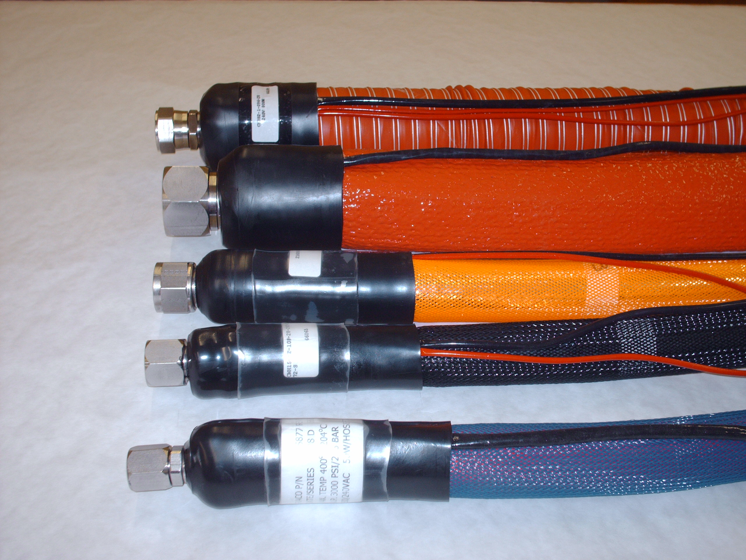
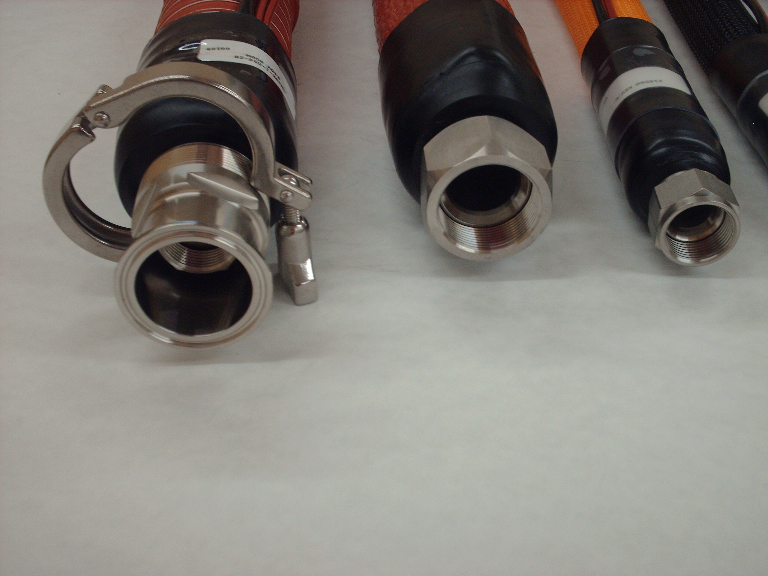
The hose end fittings are a progressive swage or crimp design and are available in Stainless Steel, Brass, or Aluminum. Choose between a Female and Male NPT, Female and Male 37o JIC Swivel, Tube stub, Cam and Groove, Sanitary Flange, BSPP and Metric or many other end fitting options.
The multi-strand heating element is comprised of a strong nickel alloy utilizing multiple end, fine gauge wire stranded design for maximum resistance to flexing while offering a large heated surface area (95%) for optimal heat transfer compared to single conductor types of heating elements. Individual strand bundles are fixed in place and insulated with flexible, high-temperature fiberglass. A layer of silicone rubber serves as an elastic cushion as well as a dielectric insulator to isolate the abrasive effects of the hose core braid.
Hose thermal insulation is provided by multiple layers of a high quality and nonflammable material which incorporates excellent temperature resistance, flexibility, and light weight while maintaining a cool running outer surface.
The outer cover of tough polyester braided jacketing serves to protect the hose, insulation, and internal components while presenting an attractive finished appearance. Other options are available, including an extruded silicone covering for water-protection as well as a variety of wire reinforced, flexible materials.
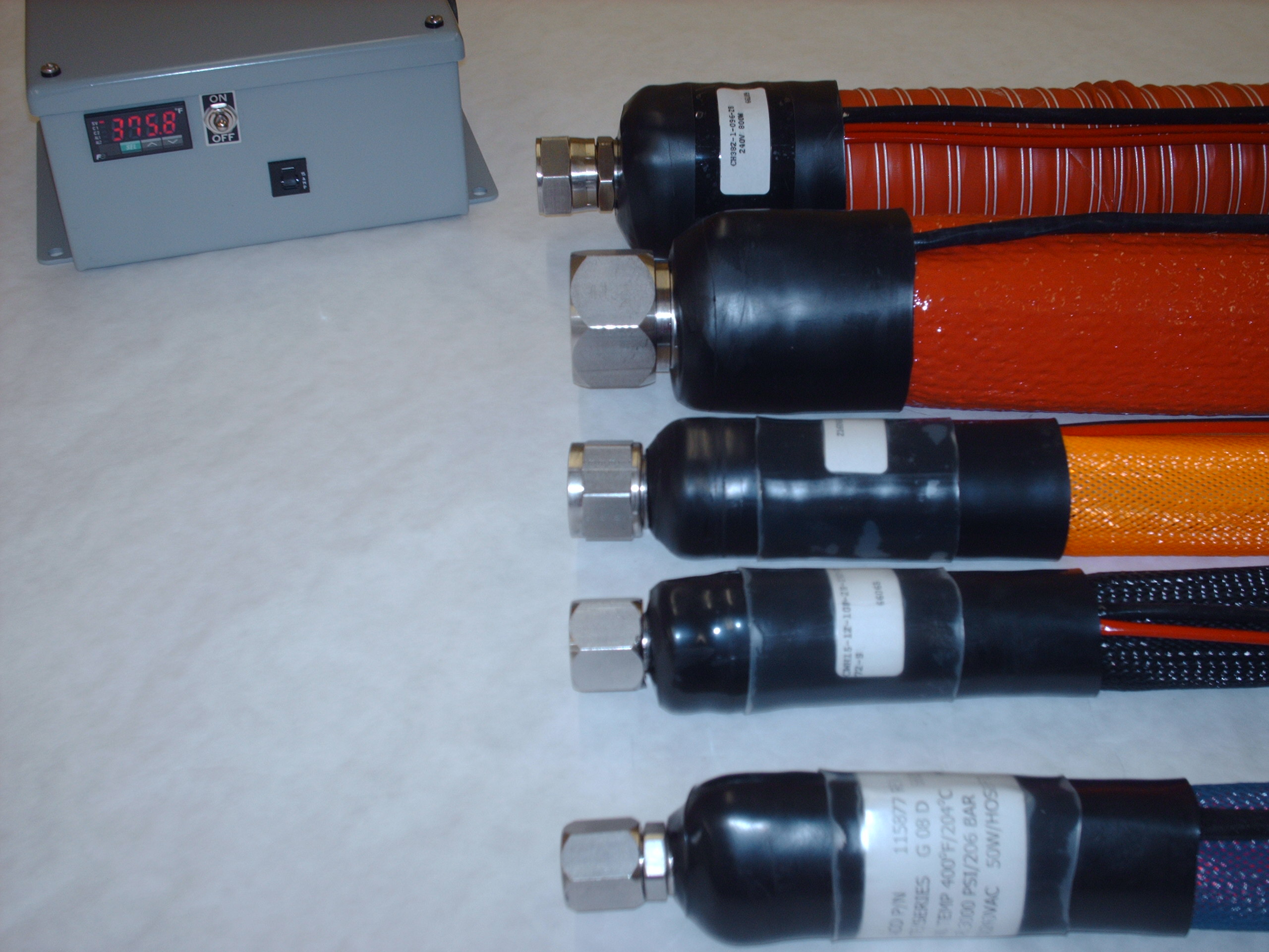
The hose ends are finished with a hardened tight fitting molded cover of Polyolefin. All integral components are bonded together within the assembly and to the hose core to prevent chemical or flexible damage and separation in use.
Heated hose electrical characteristics will match any requirement of voltage, phase and power needed. A variety of wiring options, temperature sensors, temperature controllers, and temperature control methods are available to match most requirements.
Typical Heated Hose applications include:
- Packaging Industry
- Photographic Development Solutions
- Paper Mills
- Corrugated Cardboard Lamination
- Automobile Manufacturing
- Chemical Transfer
- Automobile Emissions Testing
- Plastic and Rubber Extrusion
- Laminated Glass Manufacturing
- Two Part Foam Transfer and
- Application
- Food Transfer (FDA approved)
.
HEATED HOSE
The hose inner core is comprised of extruded PTFE or PFA Teflon®, 0.030″ or 0.040″ wall thickness, which offers exceptional resistance to temperature cycling and kinking. For those applications requiring exposure to temperatures in excess of 500°F (260 °C), hoses are furnished with an all metal, corrugated inner core and a high temperature 700°F (400 °C) resilient fiberglass heater and insulation. Additional specifications for Series CH92 high temperature hoses are available from the factory.
The hose reinforcement is provided by one or multiple layers of braided type 304 Stainless Steel wire. Nominal pressure ratings are 25% of the demonstrated burst pressure.
The hose end fittings are a progressive swage or crimp design and are available in Stainless Steel, Brass, or Aluminum. Choose between a Female and Male NPT, Female and Male 37o JIC Swivel, Tube stub, Cam and Groove, Sanitary Flange, BSPP and Metric or many other end fitting options.
The Multi-strand heating element is comprised of a strong nickel alloy utilizing multiple end, fine gauge wire stranded design for maximum resistance to flexing while offering a large heated surface area (95%) for optimal heat transfer compared to single conductor types of heating elements. Individual strand bundles are fixed in place and insulated with flexible, high-temperature fiberglass. A layer of silicone rubber serves as an elastic cushion as well as a dielectric insulator to isolate the abrasive effects of the hose core braid.
Hose thermal insulation is provided by multiple layers of a high quality and nonflammable material which incorporates excellent temperature resistance, flexibility, and light weight while maintaining a cool running outer surface.
The outer cover of tough polyester braided jacketing serves to protect the hose, insulation, and internal components while presenting an attractive finished appearance. Other options are available, including an extruded silicone covering for water-protection as well as a variety of wire reinforced, flexible materials.
The hose ends are finished with a hardened tight fitting molded cover of Polyolefin. All integral components are bonded together within the assembly and to the hose core to prevent chemical or flexible damage and separation in use.
Heated hose electrical characteristics will match any requirement of voltage, phase and power needed. A variety of wiring options, temperature sensors, temperature controllers, and temperature control methods are available to match most requirements.
Typical Heated Hose applications include:
- Packaging Industry
- Photographic Development Solutions
- Paper Mills
- Corrugated Cardboard Lamination
- Automobile Manufacturing
- Chemical Transfer
- Automobile Emissions Testing
- Plastic and Rubber Extrusion
- Laminated Glass Manufacturing
- Two Part Foam Transfer and
Application - Food Transfer (FDA approved)