704-399-4248 sales@sethermal.com

Ceramic Band Options

We offer a variety of Ceramic Band styles from standard to custom configurations. When selecting a ceramic heater, select a heater that best matches the wattage requirements – to decrease the frequency of cycling and temperature overshooting, and thereby increase the life of the heater. When installing a ceramic band heater to replace a non-insulated heater, decrease the total operating wattage by approx. 15-20 percent.


Ceramic Beads

This Ceramic band style features protective ceramic beads (encasing the lead wires ) exiting the ceramic terminal box.

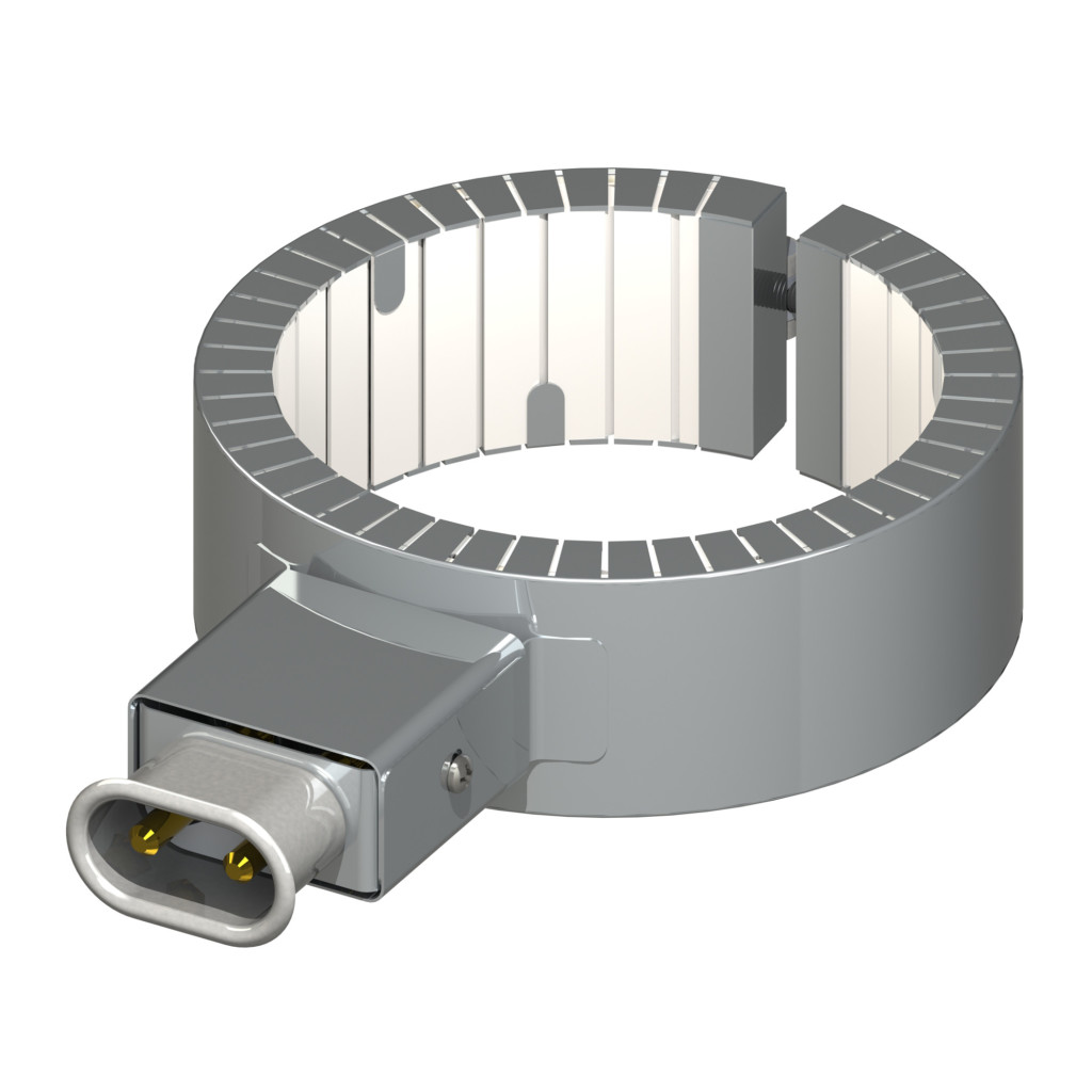
Euro Plug Ceramic Band

Ceramic Band heater with a Euro Plug (short for European) design, is an easy and safe application for applying power. This band heater design combines high temperature and the quick disconnect plug to eliminate live wiring and exposed terminals. When ordering Ceramic Euro Plug with Box – specify either a vertical or horizontal plug configuration

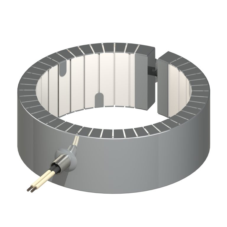
Ceramic Band Fiberglass Spring Relief

This Ceramic band heater includes fiberglass leads. The leads are covered and secured to the band by a spring relief component.

Ceramic Band Single Metal Braid

This Ceramic band heater variation bears a metal braid that provides significant flexibility and abrasion protection.

Ceramic Band Armor Cable

This Ceramic band heater style depicts fiberglass leads covered with a protective armor sleeve. The sleeve assembly is affixed to the band by a copper coupling.

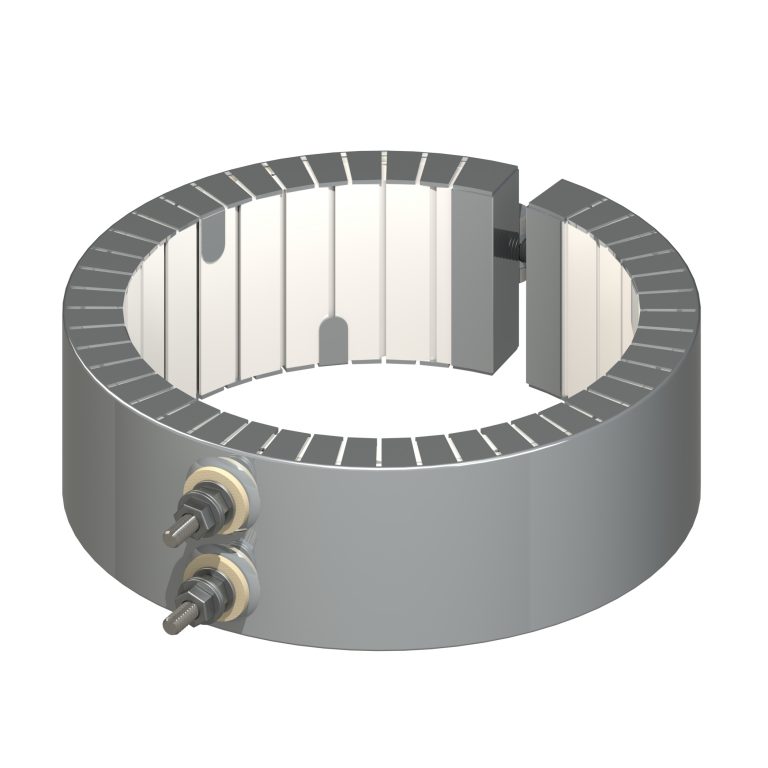
Vertical Post Ceramic Band

This Ceramic band heater style can be constructed with the terminals positioned either Vertically (above) or Horizontally. This vertical terminal design is the most common termination. The terminal location is typically  180° from the gap.

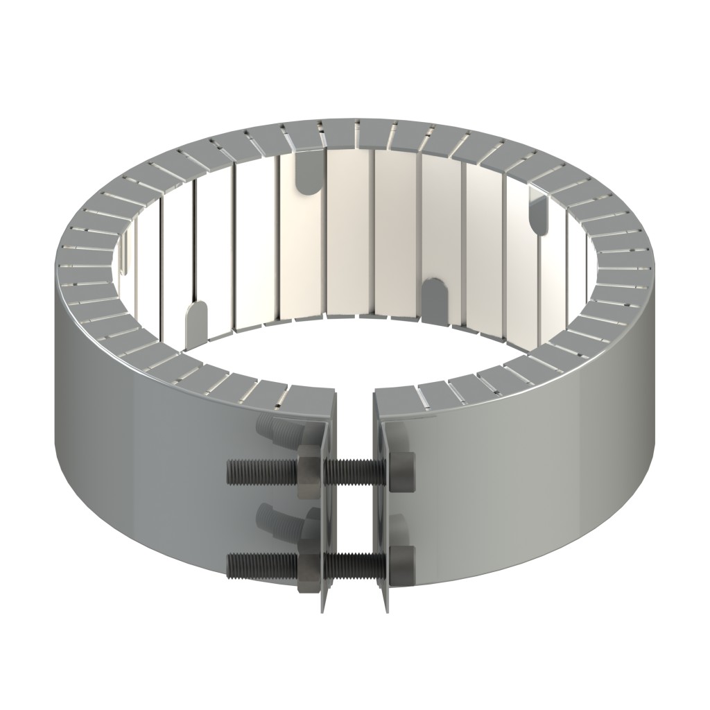
Built-in Strap Welded Barrel Nuts Ceramic Band

This Ceramic band heater is designed with a Built-in Strap Welded Barrel Nuts construction. This design is a common heating solution, and can be paired with all termination variations.

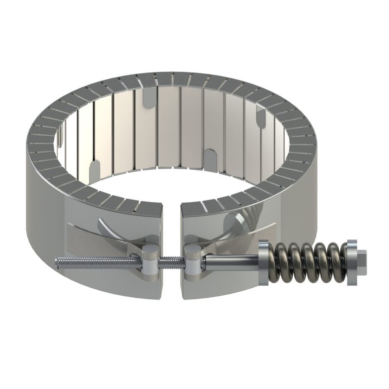
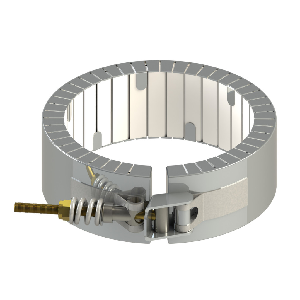
Clamping Spring Loaded Screw Ceramic Band

This Ceramic band heater construction includes spring loaded clamps to allow flexing during thermal expansion of the metals.

Flange Ceramic Band

The Ceramic Flange heater band is constructed with a bent outward Flange (Ears). This flange application is is available with all termination variations.

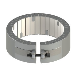
Latch and Trunion Ceramic Band

This Latch and Trunion variation is ideal for Ceramic Band Heater s exceeding 12 ” in diameter, regarding absorbing thermal expansion, and for a secure installation on large bands.

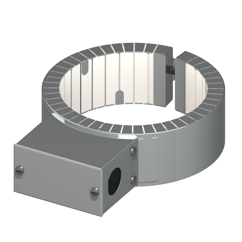
Terminal Box Ceramic Band

The Ceramic Terminal Box band heater design offers excellent protection of the terminals. The knock out holes in the T-box, make allow ease of wiring. There are several lead options available for this T-Box style.

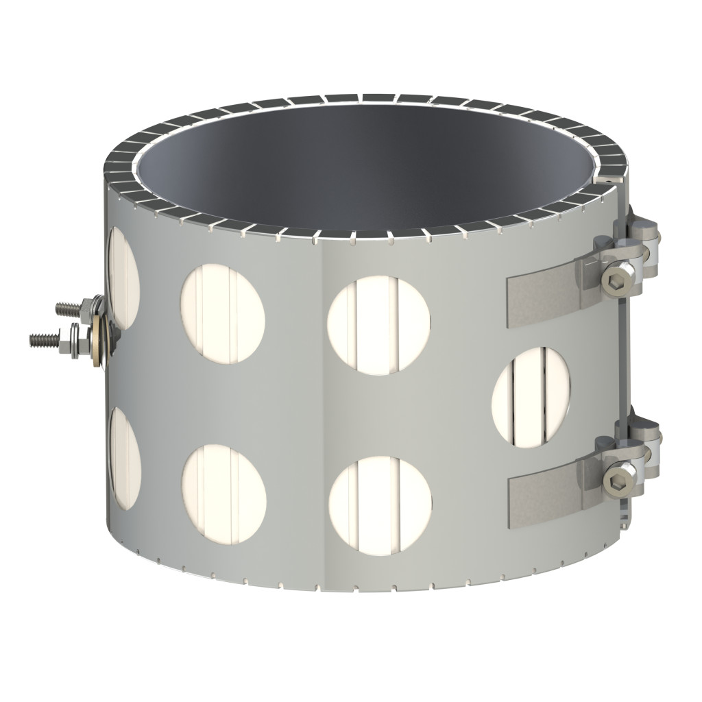
Ceramic Band with holes

This Ceramic band heater is designed with the Holes variation, and does not provide insulation. The holes in the outer band allows for more efficiency when used with forced air cooling systems.

Calculators

Power Flow Rate Temp Calculator

Calculate the electrical power, flow rate or temperature requirement.
airflow in standard cubic feet per minute
temperature rise in degrees F from the inlet to the exhaust
Watts = SCFM x ΔT/2.5

Temperature Conversion Calculator

Calculate the electrical power, flow rate or temperature requirement.
°F = ((( °C * 9) / 5 ) + 32)
°C = ((( °F - 32) * 5 ) / 9)

Three-Phase Unit Calculator

Fill in two values to find the 3rd.
W = LC * (V * √2)
V = (W / LC) / √2
LC = W / (V * √2)

Single Phase Unit Calculator

Fill in two values to find the 3rd.
W = LC * V
V = LC * W
LC = W / V

Ohms Law Calculator

Fill in two values to find the other two.

O = V / A

O = V² / W

O = W / A²

V = A * O = A * (V/A)

V = √(W * O)

V = W / A

A = V / O

A = W/ V

A = √(W / O)

W = A * V

W = V² / O

W = A² * O

Heat Transfer Through Convection Calculator

ρ = density (lb/ft3)

V = volume flow rate (ft3/hour)

Cp = specific heat (Btu/lb°F)

Ta-Tb = temperature differential (°F)

Q = ρ x V x Cp x (Ta-Tb)


Fill in four values

ρ = density (lb/ft3)
V = volume flow rate (ft3/hour)
Cp = specific heat (Btu/lb°F)
Ta-Tb = TD (°F)
Q = ρ x V x Cp x (Ta-Tb)

ACFM to SCFM

ACFM = airflow in actual cubic feet per minute

P = gage pressure (psi)

T = gas temperature °R = 460 + °F

SCFM = airflow in standard cubic feet per minute


Find Standard Cubic Feet per Minute based on data from your Actual Cubic Feet per Minute Rotameter

airflow in actual cubic feet per minute
gage pressure (psi)
gas temperature °R = 460 + °F
airflow in standard cubic feet per minute

Standard Flow Rate (SCFM) Calculator

Calculate the SCFM.
Actual cubic feet per minute
Actual pounds per square inch at Gauge
Actual temperature in °F. °R = 460 + °F
CFM * (PSI actual / 14.7psi)*(528°R / T actual)

Pressure Conversion

Fill in one value to calculate the other.
PSI = Bar * 14.504
Bar = PSI / 14.504

Mass Flow to volume Metric Flow

Fill in one value to calculate the other two
kg/h = Kilogram Per Hour (lb/min multiply by 27.216)
Lbs/min = Pounds per minute (kg/h divide by 27.216)
SCFM = Standard cubic feet per minute

Power Flow Rate Temp Calculator

Calculate the electrical power, flow rate or temperature requirement.
airflow in standard cubic feet per minute
temperature rise in degrees F from the inlet to the exhaust
Watts = SCFM x ΔT/2.5

Temperature Conversion Calculator

Calculate the electrical power, flow rate or temperature requirement.
°C = ((( °F - 32) * 5 ) / 9)
°F = ((( °C * 9) / 5 ) + 32)

Three-Phase Unit Calculator

Fill in two values to find the 3rd.
W = LC * (V * √2)
V = (W / LC) / √2
LC = W / (V * √2)

Single Phase Unit Calculator

Fill in two values to find the 3rd.
W = LC * V
V = LC * W
LC = W / V

Ohms Law Calculator

Fill in two values to find the other two.

O = V / A

O = V² / W

O = W / A²

V = A * O = A * (V/A)

V = √(W * O)

V = W / A

A = V / O

A = W/ V

A = √(W / O)

W = A * V

W = V² / O

W = A² * O

Heat Transfer Through Convection Calculator

ρ = density (lb/ft3)

V = volume flow rate (ft3/hour)

Cp = specific heat (Btu/lb°F)

Ta-Tb = temperature differential (°F)

Q = ρ x V x Cp x (Ta-Tb)


Fill in four values

ρ = density (lb/ft3)
V = volume flow rate (ft3/hour)
Cp = specific heat (Btu/lb°F)
Ta-Tb = TD (°F)
Q = ρ x V x Cp x (Ta-Tb)

ACFM to SCFM

ACFM = airflow in actual cubic feet per minute

P = gage pressure (psi)

T = gas temperature °R = 460 + °F

SCFM = airflow in standard cubic feet per minute


Find Standard Cubic Feet per Minute based on data from your Actual Cubic Feet per Minute Rotameter

airflow in actual cubic feet per minute
gage pressure (psi)
gas temperature °R = 460 + °F
airflow in standard cubic feet per minute

Standard Flow Rate (SCFM) Calculator

Calculate the SCFM.
Actual cubic feet per minute
Actual pounds per square inch at Gauge
Actual temperature in °F. °R = 460 + °F
CFM * (PSI actual / 14.7psi)*(528°R / T actual)

Pressure Conversion

Fill in one value to calculate the other.
PSI = Bar * 14.504
Bar = PSI / 14.504

Mass Flow to volume Metric Flow

Fill in one value to calculate the other two
Kg/h = Kilogram Per Hour (lb/min multiply by 27.216)
Lbs/min = Pounds per minute (kg/h divide by 27.216)
SCFM = Standard cubic feet per minute