704-399-4248 sales@sethermal.com

← Aerospace & Defense

Combustion Research

Combustion researchers today design and test new combustor shapes and configurations in an effort to optimize fuel efficiency, reduce noise and curtail pollution. At the heart of these endeavors is the redesign of the combustor inside of a turbofan engine. Heat and pressure play a critical role in the testing process.

Most of this design and testing work is initially done with simulation software. When satisfactory designs are determined, combustion researchers perform live tests of their work to prove that their models are valid. These tests will be required for FAA approval on all of the manufacturers claims and ratings.

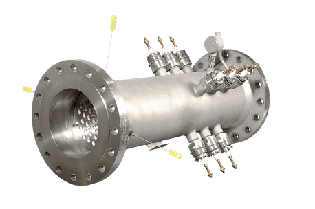
Specialty Flanged Inline Heaters have several strong advantages:
  • Serpentine technology for high temperature and high pressure.
  • We push the limits. Up to 1922°F (1050°C) is possible in a custom design.
  • No idling. No waiting. From cold heater to peak temperature in seconds.
  • Extremely fast ramp rates that are controlled.
  • Much tighter package than traditional tubular immersion units.
  • We work with you from concept to deployment and beyond.
  • Our SFI heaters are operational around the globe.
  • A strong history of proven success.

Researchers must be able to simulate the conditions of a combustor as it would be found in an operating turbo fan engine. They can’t do these tests by flying a jet so this means artificially creating high temperature and high pressure at a research facility. Combustion research testing requires many megawatts of electric power to generate the heat that simulates what’s going on inside the combustor. These facilities operate on a massive scale and take years to build, which in turn may involve years of collaboration with the client to design the heating system.

Let’s look at the test from end to end. A jet turbo engine has a combustor inside the engine. The front end of the turbo engine (the part with the big fan that we can see) is the entrance for the air that is eventually thrust out the back, providing the energy for the jet. A portion of that air gets sucked into the front end of the compressor and goes into the combustor where they introduce jet fuel and emission source. There is a large expansion of the volume that comes flying out the back end of the combustor, which turns a turbine that drives the whole process. Inside that combustor is where all the magic happens and that is the focus of these tests. Downstream of the turbo engine, researchers gather data on temperature, the amount of fuel combusted and byproducts such as NOx (nitrogen dioxide and nitric oxide) and CO.

Design and testing largely revolvers around hole and nozzle shape, quantity and configuration, fuel particle sizes and higher temperatures and pressures in the combustor. These tests are not done with a real engine. It’s just a piece of the engine. The actual unit being tested is basically a housing that’s holding the combustor shape, which includes the combustor, the combustor nozzles and a way to introduce the fuel. Combustion researchers will constantly adjust and tune the design as they run these tests.

High temperature heaters are critical components in combustor testing. They must be able to ramp quickly, heat a airflow to a very high temperature, withstand high pressures, hold a steady temperature and perform with consistency. Heater Design Engineers are being asked to push the boundaries of what was previously possible. Yesterday’s record-breaking ramp rates are old news in the global quest for greater fuel efficiency and pollution reduction in turbofan engines.

Industry Brief:

  • up to 1652°F (900°C) in standard designs
  • up to 1922°F (1050°C) in custom designs
  • up to 600psi (40 Bar) standard
  • greater than 1100psi (75 Bar) custom
  • open coil serpentine elements ramp fast

These are research applications requiring very high temperatures, very high pressures and consistency.

Calculators

Power Flow Rate Temp Calculator

Calculate the electrical power, flow rate or temperature requirement.
airflow in standard cubic feet per minute
temperature rise in degrees F from the inlet to the exhaust
Watts = SCFM x ΔT/2.5

Temperature Conversion Calculator

Calculate the electrical power, flow rate or temperature requirement.
°F = ((( °C * 9) / 5 ) + 32)
°C = ((( °F - 32) * 5 ) / 9)

Three-Phase Unit Calculator

Fill in two values to find the 3rd.
W = LC * (V * √2)
V = (W / LC) / √2
LC = W / (V * √2)

Single Phase Unit Calculator

Fill in two values to find the 3rd.
W = LC * V
V = LC * W
LC = W / V

Ohms Law Calculator

Fill in two values to find the other two.

O = V / A

O = V² / W

O = W / A²

V = A * O = A * (V/A)

V = √(W * O)

V = W / A

A = V / O

A = W/ V

A = √(W / O)

W = A * V

W = V² / O

W = A² * O

Heat Transfer Through Convection Calculator

ρ = density (lb/ft3)

V = volume flow rate (ft3/hour)

Cp = specific heat (Btu/lb°F)

Ta-Tb = temperature differential (°F)

Q = ρ x V x Cp x (Ta-Tb)


Fill in four values

ρ = density (lb/ft3)
V = volume flow rate (ft3/hour)
Cp = specific heat (Btu/lb°F)
Ta-Tb = TD (°F)
Q = ρ x V x Cp x (Ta-Tb)

ACFM to SCFM

ACFM = airflow in actual cubic feet per minute

P = gage pressure (psi)

T = gas temperature °R = 460 + °F

SCFM = airflow in standard cubic feet per minute


Find Standard Cubic Feet per Minute based on data from your Actual Cubic Feet per Minute Rotameter

airflow in actual cubic feet per minute
gage pressure (psi)
gas temperature °R = 460 + °F
airflow in standard cubic feet per minute

Standard Flow Rate (SCFM) Calculator

Calculate the SCFM.
Actual cubic feet per minute
Actual pounds per square inch at Gauge
Actual temperature in °F. °R = 460 + °F
CFM * (PSI actual / 14.7psi)*(528°R / T actual)

Pressure Conversion

Fill in one value to calculate the other.
PSI = Bar * 14.504
Bar = PSI / 14.504

Mass Flow to volume Metric Flow

Fill in one value to calculate the other two
kg/h = Kilogram Per Hour (lb/min multiply by 27.216)
Lbs/min = Pounds per minute (kg/h divide by 27.216)
SCFM = Standard cubic feet per minute

Power Flow Rate Temp Calculator

Calculate the electrical power, flow rate or temperature requirement.
airflow in standard cubic feet per minute
temperature rise in degrees F from the inlet to the exhaust
Watts = SCFM x ΔT/2.5

Temperature Conversion Calculator

Calculate the electrical power, flow rate or temperature requirement.
°C = ((( °F - 32) * 5 ) / 9)
°F = ((( °C * 9) / 5 ) + 32)

Three-Phase Unit Calculator

Fill in two values to find the 3rd.
W = LC * (V * √2)
V = (W / LC) / √2
LC = W / (V * √2)

Single Phase Unit Calculator

Fill in two values to find the 3rd.
W = LC * V
V = LC * W
LC = W / V

Ohms Law Calculator

Fill in two values to find the other two.

O = V / A

O = V² / W

O = W / A²

V = A * O = A * (V/A)

V = √(W * O)

V = W / A

A = V / O

A = W/ V

A = √(W / O)

W = A * V

W = V² / O

W = A² * O

Heat Transfer Through Convection Calculator

ρ = density (lb/ft3)

V = volume flow rate (ft3/hour)

Cp = specific heat (Btu/lb°F)

Ta-Tb = temperature differential (°F)

Q = ρ x V x Cp x (Ta-Tb)


Fill in four values

ρ = density (lb/ft3)
V = volume flow rate (ft3/hour)
Cp = specific heat (Btu/lb°F)
Ta-Tb = TD (°F)
Q = ρ x V x Cp x (Ta-Tb)

ACFM to SCFM

ACFM = airflow in actual cubic feet per minute

P = gage pressure (psi)

T = gas temperature °R = 460 + °F

SCFM = airflow in standard cubic feet per minute


Find Standard Cubic Feet per Minute based on data from your Actual Cubic Feet per Minute Rotameter

airflow in actual cubic feet per minute
gage pressure (psi)
gas temperature °R = 460 + °F
airflow in standard cubic feet per minute

Standard Flow Rate (SCFM) Calculator

Calculate the SCFM.
Actual cubic feet per minute
Actual pounds per square inch at Gauge
Actual temperature in °F. °R = 460 + °F
CFM * (PSI actual / 14.7psi)*(528°R / T actual)

Pressure Conversion

Fill in one value to calculate the other.
PSI = Bar * 14.504
Bar = PSI / 14.504

Mass Flow to volume Metric Flow

Fill in one value to calculate the other two
Kg/h = Kilogram Per Hour (lb/min multiply by 27.216)
Lbs/min = Pounds per minute (kg/h divide by 27.216)
SCFM = Standard cubic feet per minute