← MICA BAND HEATERS
MINERAL BAND HEATERS→
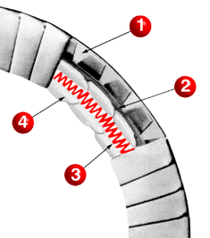
STANDARD CERAMIC BAND HEATERS
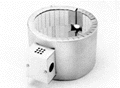
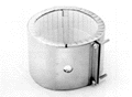
Plastic processing requires high operating temperatures and fast production rates. The Ceramic Band Heaters are designed to meet these demands. These heater are, in effect, high temperature electric furnaces capable of very efficient heat transfer by radiation, conduction and convection. Built-in insulation minimizes unwanted temperature changes along the barrel.
Other types of band heaters are primarily conductive, requiring an intimate fit with components being heated. Grooves or other surface irregularities form voids under the bands, resulting in hot spots and premature heater failure. Ceramic bands are recommended here because efficient heat transfer is not affected by irregular surfaces or loose fit. At higher watt densities they can be used in wider increments than other heaters. This means you can reduce the number of bands used and simplify wiring.


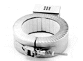
Stainless Steel Sheath: Resists rust and high temperatures, and provides firm mechanical support. Easily wraps around barrel due to fluted construction.
Ceramic Fiber Thermal Insulation
¼ inch of ceramic fiber prevents heat loss, thereby lowering energy costs.
Ceramic Coil Supports
Designed for their dielectric and thermo-conductive characteristics, the interlocking feature provides flexibility so band wraps easily around barrel.
Nickel-Chrome Heating Coil
Precision wound, helical construction gives extended service. A heavier weight than found in mica or other conventional heaters.
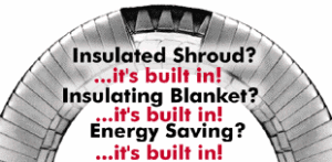
insulation plus ceramic band "The Energy Saver"
- Insulation Plus employs an additional 1/4″ of thermal insulation encased in a separate flexible stainless steel shell.
- Standard 1/4″ thick thermal insulation found on all ceramic band heaters.
- Helical nickel-chrome coil for extended service.
- Ceramic coil supports.
COOLER AMBIENT TEMPERATURES AROUND THE OPERATING MACHINES
 Stud Terminals in Low Profile Box (1″ High) With BX installed |
 Stud Terminals in Standard Two Terminal Box (1-3/4″ High) |
 Standard Flange Lock-Up |
 Optional spring Loaded Latch and Trunnion Lock-Up For Large Diameter Bands. |
 Stud Terminals in Standard Three Terminal Box (1-3/4″) |
 Thermo Couple Hole in Gap Shell Overlap With Lock-up |
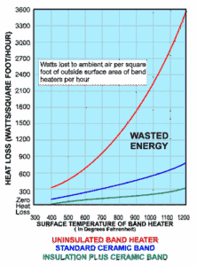
COMPARISON OF INSULATED VERSUS NON-INSULATED
BANDS IN TERMS OF WASTED ENERGY
Super Insulation Plus
1-1/4″ thick, 7/8″ thermal insulation, up to 40 watts/sq. in.Super Insulation Plus employs an additional 5/8 inch of thermal insulation encased in a separate flexible stainless steel shell.
“MAXIMUM ENERGY SAVINGS, MINIMUM SHEATH TEMPERATURES”
ultra thin ceramic bands
High performance heater band for processing high temperature engineering resins. “Ultra-Thin” heater bands have the same basic construction as our standard ceramic heaters except they are much thinner and have a high ratio of thermal to electrical insulation. The thin ceramic insulation used results in a lower mass construction, which improves response to control and minimizes temperature lag and overshoot. The backside thermal insulation is highly efficient and results in minimal heat loss and lower sheath temperature.
Special Note:
These are completely flexible radiant heaters. Heavy clamping pressures are not required regardless of heater size. No need for hinged, two piece, or expandable designs associated with mineral insulated (MI), mica or other conduction type heaters.
SPECIFICATIONS
Insulation – 3/16″ thick thermal insulation (ceramic fiber)
Sizes – Minimum 1D 1-1/2″ (38.1mm) 1″ wide and up
Terminals – Post Terminals Standard ( 10-24 Thread or 1/4″-20 Thread)
Sheath – Stainless Steel
Lock-up – Flange or Barrel Nut Standard
Standard Gap – 1/4″ when tightened
Metric Sizes available
Wall Thickness – 11/32″ (+1/32″, -.00)
Temperature – Up to 1400 Deg. F
Watt Density – Up to 65W/Sq. in. (9.9 W/C2)
Voltage – Up to 480 V (Single or three phase)
Resistance-Tolerance +10%-5%
Wattage Tolerance +5%-10%
Maximum Amperage – 20/Circuit
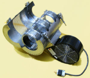
air cooled ceramic bands
Super-efficient and economical air cooled ceramic heater bands are designed for use on extrusion machinery or on any heat/cool operation. They feature 63% open perforated metal sheath, which assures maximum surface area exposure. They also provide the user with a more economical operation, via a rapid heat-up and cool-down feature. Their “Black Star” coating further increases efficiency. Advantages of air cooled vs. Liquid cooled operation include: lower cost, replaceable heaters, low maintenance, no leak problems, and close temperature control.
 SPECIFICATIONS
Temperature – Up to 1400 Deg. F
Watt Density -Up to 45 W/Sq. In.
Voltage – Up to 480 V (single or three phase)
Resistance -Tolerance NEMA Standard plus 10% Minus 5%
Wattage Tolerance – NEMA Standard plus 5%, Minus 10%
Maximum Amperage – 25/Circuit
Sizes – 2″ dia. And up: 1-1/2″ width and up (in 1/2″ increments
Terminals – 1/4″-20 post terminals standard
Sheath – Aluminized steel
Lock-up – Flange type steel
Maximum ID – Consult factory
Standard width increments -1/2″
Standard gap when tightened – 1/4″
Thickness – 1/2″